Roomba PAD LIFT mechanism
iRobot | Mechanical Engineer | July - December 2022

OBJECTIVE
This was a system-level project that involved multiple component efforts. Some of those efforts included:
1. Worst-case current testing and risk mitigation
2. Gearbox assembly issue and solution
3. Redesigning a metal injection molded (MIM) gear to be co-molded for cost savings
SKILLS SNAPSHOT
DFM/DFA
PTC CREO
PLASTIC INJECTION MOLDING
SURFACE MODELING
ELECTROMECHANICAL SYSTEMS
RISK MANAGEMENT
FAILURE TESTING
PROCESS IMPROVEMENT
WORST-CASE CURRENT TESTING & RISK MITIGATION
I led the effort to assess a potential risk with the pad lift mechanism: as the wheels wear down over time and the robot rides lower, there is a risk that the bin drags over a threshold and causes damage to the home or the robot. This would also incur a current error that would stop the robot's cleaning pass and require human intervention.
Objective
Troubleshooting Steps
-
Went through the previous engineer's notes and set out to replicate his results
-
Taught myself to use iRobot's internal debugging and control software
-
Ran a robot over thresholds in the office without incurring the error
-
Ran a robot over the highest allowable threshold in the product specs without incurring the error
-
Expanded my fleet to five robots and conducted the threshold test with a full debris bin, but did not incur the error
-
3D printed two alternate bins (one with a lower profile, and another with "ramp" features) and tested, but saw no difference with the existing bin
-
Communicated with our manufacturing partners in China to procure 10X worn wheel modules from production lifetime testing to assemble into my fleet or robots, but did not incur the error
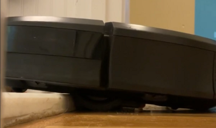
The robot riding low over a threshold. If it rides too low, the threshold or the robot could become damaged. The robot could also throw a high current error that requires manual intervention. (Photo credit: Youtube - Robot Master)

Worn wheels like those I procured from our Chinese manufacturers to sub into my fleet of robots (Photo credit: r/roomba)
RESULTS
-
My test results proved the risk was negligible, so redesigning parts and investing in new tooling was not worthwhile. I recommended against taking further action.
-
The effort contributed to my being approved for a promotion to Senior Mechanical Engineer
-
I received the following feedback:
-
"Taylor takes ownership of her technical tasks. Her dedication to getting to the root of issues and fully understanding the solution set is commendable."
-
"A colleague was impressed that Taylor ordered worn wheel modules to use in testing... this was an above and beyond way to bound the data set, and provided additional confidence in the decision to forgo a solution because the existing product issue is not subject to degradation over life."
-
GEARBOX ASSEMBLY ISSUE AND SOLUTION
To find the root cause of a series of unexpected and seemingly random current draw errors.
Objective
Troubleshooting Steps
-
Tore down multiple pad lift gearboxes (left and right on multiple robots)
-
Documented anomalies (amount of lubrication, debris, etc)
-
Determined that the Geneva gear could be assembled one tooth off, which caused one side's wheel lift shim to deploy ahead of the other
-
Alerted the manufacturing team of the assembly issue
-
Implemented a pokayoke feature to eliminate risk of assembling the geneva gear one tooth off
Results
-
The high current issue was resolved when I alerted the manufacturing team and implemented a pokayoke on the assembly fixture moving forward!

The pad lift mechanism (photo credit: eBay)

A pad lift gearbox: the geneva gear on one side was sometimes assembled one tooth off, so that one side's wheel lift shim deployed ahead of the other and caused a high current error
GEAR MATERIAL TRANSITION
To redesign the driven gear from being metal injection molded (MIM) to being co-molded for cost savings.
Objective
Design Steps
-
Split the solid-body CAD into two separate bodies, a MIM core and a co-molded portion
-
Improved DFM with our manufacturing partners in China
-
Added 11 passthroughs and validated adhesion in pre-production samples
-
Results
-
My co-molded version of the gear was fully validated for production
-
The material changes saved $0.442 per gear, or $0.884 per production robot

The original MIM compound gear

The final co-molded compound gear, front and back