ROTARY VANE PUMP BUILD
Boston University | Candidate for M.S. in Product Design & Manufacture | Fall 2023
OBJECTIVE
I was given a design for a rotary vane pump so that I could manufacture each part during lab sessions throughout the semester. My overarching goal was to build a functional pump at the end of the semester, without needing any major reworks after beginning the assembly process.
SKILLS SNAPSHOT
MILLING
TURNING
LASER CUTTING
WATER JETTING
SAND CASTING
RIVETS
SHEET METAL BENDING
HELICOILS
DESIGN STEPS
-
Turning parts: shaft, rotor, housing, front plate
-
Milling parts: vanes (4X), housing
-
Sandcasting parts: rear bearing housing
-
Sheet metal bending: two-part stand
-
Waterjet parts: front ring
-
Laser cutting parts: gasket (2X)
-
Assembly operations: riveting, helicoils, press fits for bearings (2X) and shaft seal
RESULTS
-
I learned to produce parts using manufacturing processes I hadn't tried before - sandcasting and sheet metal bending were entirely new to me, and I feel much more confident in my machining on a mill or a lathe than I did before
-
I developed a healthy respect for how designs inform manufacturing set ups
-
My pump worked! It delivered a steady stream of fluid out its exit port, and it did not leak at any of its interfaces.
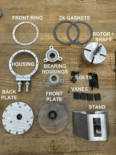
The parts of my pump before assembly (not pictured: the nuts, which would secure the bolts and be seated against the back plate).

Three views of my pump: the body sits in a sheet metal stand riveted to a divider between the inlet and outlet ports. The back plate is transparent so that you can watch the vanes being flung outward by the centrifugal force imparted by the drill chuck on the hex end of the shaft. The vanes seal against the inner diameter of the outer ring, creating varying volumes of moving fluid.
OPPORTUNITIES FOR IMPROVEMENT
-
Milling - Chamfers:
-
My first attempt looked like I had cut a step into the edge, rather than a chamfer, because my cutter was at the wrong angle
-
I likely finished facing the ends of my shaft and went straight to applying my "chamfer", without realizing I needed to adjust the angle of my cutter
-
I adjusted my cutter and was able to create a correct chamfer on the other side of my shaft
-
-
Milling - Hex Shaft Interface
-
When machining each face of the hex, we were told that doing the length by eye was fine. My eye wasn't perfect and I ended up cutting further than I should have, which left a gash on the face at the root of my hex
-
I learned to be more conservative and to "sneak up on" where the end of the cut should be
-
If I were to do this again, I could have set the digital readout (DRO) to zero once I finished putting the first flat face on the hex. For subsequent cuts, I could have monitored the readout on the DRO in Y until it hit zero again, which would have meant all my hex lengths were identical within 0.001"
-

Shaft chamfers: you can see the incorrect "step" on the right side of the large OD, and the correct chamfer on the left side of the large OD

Hex shaft interface: you can see the incorrect cut into the flat face of the shaft, past where the hex should end
-
Sand casting
-
The finish on the outer portion of my sandcast part was not ideal, though functionally it was ok
-
In the future, I could remake the pattern myself or refinish the existing pattern I was given. The pattern we were given was 3d printed and had been used over the years, so it's surface finish had deteriorated (which in turn meant the sand cast parts inherited that poor surface finish)
-


There are unintentional voids and chamfers around the exterior surfaces of the part. They don't affect functionality, but I'd like to improve on the texture with a new mold, especially if this were to be a customer facing part in a real-world application
-
Waterjet front ring:
-
The first time I waterjet the front ring, I mistakenly only engaged two out of the three possible locks to keep my material in one place
-
Once the waterjet started and my view into the bed was obscured by water droplets and abrasive, I couldn't tell that the material had moved and my front ring had failed until the end of the 20-minute run time
-
I repeated the waterjet operation, this time ensuring that all possible locks were used to keep the material stationary
-
I learned to double - even triple! - check the fixturing of a new part. In this case I hadn't even known there was a third lock to engage, so I ended up wasting some time and material because of my mistake
-

My initial (very) failed front ring, due to poor clamping

The corrected front ring installed on the pump